Fluid Hydraulics (Part 3): Pressure and Head
In Parts 1 and 2 of Fluid Hydraulics, we discussed specific gravity, vapor pressure, and volatile substances. Today we are going to wrap things up with two other factors that affect the fluids you pump through your hydraulic equipment — pressure and head.
To recap, a hydraulic pump is a mechanical device that converts mechanical power into hydraulic energy — generating flow with enough power to overcome pressure induced by the load.
Remember, a pump produces liquid movement (or flow) — it does not generate pressure. It simply creates the flow necessary for the development of pressure. Instead, pressure is a measurement of the resistance to flow and flow is dependent upon the pumps’ system characteristics.
PRESSURE WILL VARY
Pressure, or resistance to flow, will vary greatly depending on the type of pump being used. For instance, centrifugal pumps, also known as non-positive-displacement or hydrodynamic pumps, produce a continuous flow. However, because they do not provide a positive internal seal against slippage, their output varies considerably as pressure varies.
Positive displacement pumps, also referred to as Hydrostatic pumps, convert mechanical energy to hydraulic energy with a comparatively small quantity and velocity of liquid. With hydrostatic pumps, output pressure actually depends on the velocity at which the liquid is made to flow.
HYDRAULIC HEAD
Hydraulic head is a specific measurement of liquid pressure above a geodetic datum. Head is equal to the fluid’s energy per unit weight and is useful in specifying centrifugal pumps because their pumping characteristics tend to be independent of the fluid’s density.
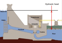
Source: http://en.wikipedia.org/wiki/Hydraulic_head
The above image shows the available difference in hydraulic head across a hydroelectric dam before head is lost due to turbines, wall friction and turbulence. The below image simplifies this concept a bit more.
Source: http://en.wikipedia.org/wiki/Hydraulic_head
Above we see fluid flowing from the top of a tank to the bottom basin while under the pressure caused by the hydraulic head.
There are four types of head used to calculate the total head in and out of a pump:
- Velocity head is due to the general motion of a fluid.
- Elevation head is due to the fluid’s weight.
- Pressure head is due to the static pressure (the internal molecular motion of a fluid that exerts a force on its container).
- Resistance head (or friction head) is due to the frictional forces acting against a fluid’s motion inside the container.
By educating our customers about the machinery they rely on for their day-to-day operations, C&B Equipment can help increase uptime, while decreasing the need for costly off-site repairs. That’s what we call Uptime Solutioneering™.